Spreekt praktisch voor zich, Nederlandse tekst volgt later!
Klik op de foto’s om te vergroten.
Source Cummins Publication Issue HTi_06
(use keyword ‘magazines’ to go direct to this section with interesting Cummins publications on this website, choose HTi_06 with more interesting information regarding Telemetry)
Producing a shaft and wheel to meet such specific demands is a technique that has been developed and refined by our manufacturing engineers over many years.
The shaft and wheel is a core component, necessarily manufactured in-house, where years of experience have gone into the critical production processes needed to ensure our quality based reputation.
How is a shaft and wheel manufactured?
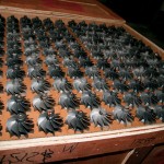
Perhaps the most vital component at the beginning of the manufacturing process is the Inconel austenitic nickel-chromium-iron alloy turbine wheel, a high strength investment casting.
Inconel is a material that manufacturing engineers dislike.
It is designed to withstand high temperatures, with an inevitable trade-off in machineability.
Therefore a casting process has been developed and progressively refined to provide a casting profile that requires minimal machining.
In practice, the only turbine wheel machining undertaken inhouse by Cummins Turbo Technologies is to ‘mass centre’ the hole in the nose of the wheel.
As the name implies the hole is positioned at the centre of mass of the casting, not at its geometric centre, in order to ensure perfect balance in the finished component.
The centre hole is used to locate the turbine wheel throughout the manufacturing processes.
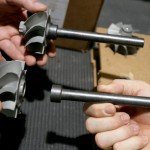
Starting life as a steel forging, the shaft is friction welded to the turbine wheel.
Friction welding was developed in the 1980s as a relatively low cost and reliable welding process, which proved ideal for attaching a turbocharger’s comparatively soft steel shaft to the much harder turbine wheel investment casting.
More traditional welding techniques had proved less than satisfactory, but intensive development of friction welding led to a process that is consistent and reliable.
During the process, friction between a rotating and a stationary component causes the two metals to become red hot, at which stage pressure is applied to forge the parts together.
Typically the shaft length is reduced by 3mm during the process.
Quality is controlled by careful monitoring of the process parameters, notably speed and pressure. To ensure effective process control, random samples of the conjoined turbine/shaft component are regularly tensile tested to destruction.
Surprisingly, a typical friction welded joint with a surface area of only 2cm sq will take a tensile load of over 10 tonnes before fracture.
Furthermore, the joint is usually stronger than the parent metal.
Welding is followed by turning the shaft diameters in a lathe prior to precision grinding to finished tolerances.
Before grinding, the bearing diameter of the shaft is induction hardened to provide the required durable surface match for the journal bearings.
Induction hardening produces a hard surface on the shaft up to 2mm deep, while retaining a softer inner core in the shaft to maintain strength against potential shock load fracture.
Final grinding of shaft diameters is done on CNC (computer numerical control) grinding machines able to work to the required size, straightness and roundness tolerances on all shaft diameters.
Quality is assured through the use of multiple function electronic gauges able to measure all the vital dimensions simultaneously.
Statistical process control and calculation of the ongoing capability of the process is provided at the same time.
After the shaft diameters have been finish ground, the turbine wheel profile must be machined; another specialised Inconel machining operation.
The hardness of the material means that the profile must be ground.
Tolerances on size and concentricity must be maintained during the process to ensure an accurate match between the turbine wheel and its housing, thereby guaranteeing consistently high turbine efficiency.
Seal ring grooves in the hub of the shaft may be turned or ground.
Once again tight tolerances are essential on dimensions and surface quality as they influence oil leakage control in the finished turbocharger.
Threads are then rolled on to the impeller end of the shaft. A strong concentric thread is required to retain the impeller, especially so in the face of customer demand for increased turbocharger performance necessitating larger impellers with small compressor clearances.
The final manufacturing operation is to balance the turbine wheel so that the shaft and wheel assembly is capable of running at operating speeds without vibration or excessive shaft movement in the bearing system.
The shaft is dynamically balanced in two planes; at the nose and back face of the turbine wheel.
This is undertaken on semi or fully automatic machines that measure balance of the turbine wheel, simultaneously calculating the precise amount of material required to be ground from each plane of the turbine wheel to bring it into balance.
Almost every dimension on the shaft and wheel is critical to turbocharger performance and durability.
The manufacturing tolerances being achieved today are close to the best achievable in any volume manufacturing process.
Manufacturing processes developed by Cummins Turbo Technologies are applied globally to provide durable high quality components at the most economic cost.
Almost every dimension on the shaft and wheel is critical to turbocharger performance!!


